
News


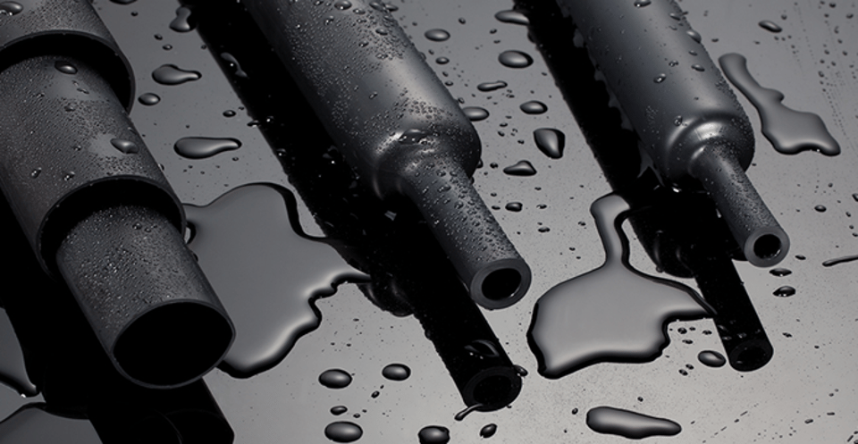
Is Heat Shrink Tubing Waterproof?
Is Heat Shrink Tubing Waterproof? Common Misconceptions 1. Standard Single-Wall Tubing: Water-Resistant, Not Waterproof Standard, single-wall heat shrink tubing is water-resistant, but it does not provide a truly waterproof seal. The polyolefin material itself is non-porous and highly resistant to moisture, meaning it will easily shed splashes, condensation, and humidity without absorbing the water. This level of protection is often sufficient for applications inside an enclosure or where only incidental contact with moisture is expected. The primary limitation of standard tubing lies in the method of sealing at the ends of the tube, where the cable enters the sleeve. Not all heat shrink tubing is waterproof by default. Single-wall heat shrink tubing does provide protection against moisture, but is not completely waterproof. 2. The Solution: Adhesive-Lined (Dual-Wall) Heat Shrink Tubing If you want a truly waterproof seal, choose medium-wall heat shrink tubing with adhesive. This contains an inner layer that melts and adheres to the cables when heated, creating a strong, waterproof seal — ideal for outdoor use, humid environments, or underground applications. The thermoplastic adhesive has a low melting point, allowing it to fully activate before the outer polyolefin layer is damaged by excessive heat. As the tubing cools, the adhesive solidifies, creating a robust, non-reversible bond that seals the ends and encapsulates the entire connection. The glued heat shrinkable tube can be sealed, waterproof, dustproof, and air-leak proof. Even if the entire product protected by the glued heat shrinkable tube is placed in water, water will not be able to enter its interior. The waterproof level can reach IP67. 3. Shrink Ratio Matters for a Proper Seal Selecting the correct shrink ratio is also a factor in achieving a waterproof level of sealing. Ratios like 3:1 or 4:1 allow the tubing to shrink significantly more than standard tubing, which is essential for irregular shapes like soldered wire bundles or bulky connector joints. If you only have ordinary heat-shrinkable tubing on hand and the waterproof requirements are not very high, you can use electrical tape to wrap 3–4 layers tightly around the port after shrinking the heat-shrinkable tubing to increase reliability. 4. Comparison: Standard vs Adhesive-Lined Heat Shrink Tubing Parameter Standard Single-Wall Adhesive-Lined (Dual-Wall) Water Protection Water-resistant only (no end seal) Fully waterproof — IP67 capable End Sealing Open ends — moisture can enter Adhesive melts and fills all gaps Shrink Ratio Typically 2:1 3:1 or 4:1 — suits irregular shapes Working Temp. Up to 125°C (standard polyolefin) 125°C rated / 160°C overload (4hr) Typical Use Indoor, enclosures, incidental moisture Marine, outdoor, underground, automotive Cost Lower 20–40% higher — reflects superior seal
8/28, 2026
read more
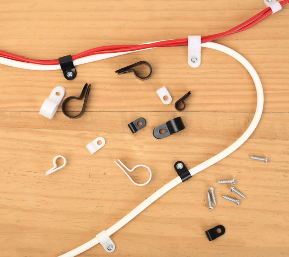
Why Cables Need Cable Clamps
Cable clamps are essential cable management tools that secure, organize, and protect cables across residential, automotive, industrial, and outdoor environments. They prevent cable movement, strain, and abrasion, reducing the risk of electrical failures, safety hazards, and equipment damage. 1. Prevent Cable Movement & Wear Their primary function is to prevent cables from moving or shifting, which can cause wear and tear or disrupt the electrical flow. In instances where vibrations are prevalent, such as in automotive or machinery environments, cable clamps become particularly important. They counteract the displacement of cables due to motion, which might otherwise lead to significant electrical disruptions. Proper cable support prevents excessive bending, vibration, and friction, all of which can degrade cable insulation over time. 2. Reduce Fire & Short-Circuit Risk A cable clamp protects the cable from abrasion, cuts, or nicks that could expose the conductors and create a fire hazard or a shock hazard. It prevents strain on the cable and its connections, which could cause loose wires, arcing, overheating, or short circuits. 3. Distribute Mechanical Stress Evenly Cable clamps help distribute physical and mechanical stress evenly across wires, preventing concentrated stress points that can result in injuries or accidents. Electrical installation standards emphasize the importance of securing cables to prevent strain on connections and reduce mechanical stress that can lead to system failures. 4. Protect Against Harsh Environments Cables in industrial environments are often exposed to extreme conditions. Cable clamps protect cables from these stresses by keeping them securely fastened in place, reducing the risk of damage caused by friction, bending, or excessive tension. Weather-resistant clamps protect cables from moisture, corrosion, and UV exposure in outdoor and marine installations. 5. Support Heat Dissipation & Signal Integrity Spacing cable clamps properly is crucial for effective heat dissipation and preventing potential overheating of cables during operation. Incorrect spacing often leads to overheating, causing degradation in cable integrity and performance. Compliance with industry standards like ANSI/TIA-568 dictates the use of specific cable management techniques to avoid cable stress and maintain system longevity. 6. Applications by Environment Environment Role of Cable Clamps Residential Secure cables in junction boxes; comply with NEC Sec. 314.17(C); prevent fraying and fire hazard Automotive Secure wiring harnesses; protect from vibration, heat, and movement; prevent engine interference Industrial Prevent cable entanglement on machinery; reduce wear; improve workplace safety and uptime Outdoor / Marine Resist moisture, corrosion, and UV degradation in exposed environments Data / Telecom Maintain signal integrity; prevent bend-radius violations per ANSI/TIA-568
8/21, 2026
read more
What Happens If Heat Is Applied Unevenly?
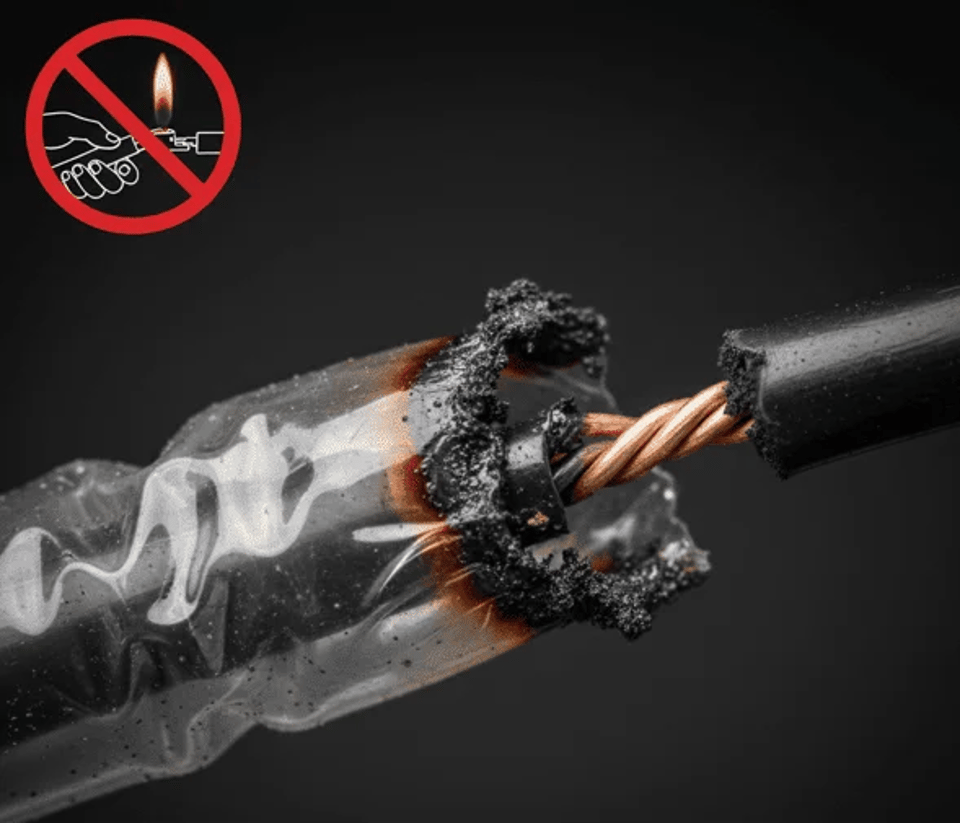
"The most frequent error is starting at the ends instead of the middle, which traps air and creates bubbles." PROBLEM 1 — OVERHEATING Too much heat causes the tubing to thin unevenly, curl at the edges, or take on that shiny, scorched look. If it smells, this is your culprit, too. Open flames and high-output heat guns create hot spots that blast one area while the rest barely shrinks. That's why one side of your heat shrink can look overcooked while the other still looks thick. Overheating happens fast when the heat source is too close or stays in one spot too long. This happens when you hold the heat gun too close or in one spot too long. The tubing becomes glossy, then may char or melt, making it brittle. Signs: Burn marks, charring, blistering, cracking, shiny surface, or strong odor Risk: Compromised dielectric strength and mechanical protection — the connection is no longer reliably insulated PROBLEM 2 — UNDERHEATING When the tubing doesn't get enough consistent heat, it never fully conforms to the wire underneath. The walls stay thick and soft, air gets trapped inside, and the ends don't seal the way they should. You'll see uneven shrinkage, open gaps, or that slightly inflated look where the tubing tightened in some spots but not others. Underheating heat shrink is very common when the heat source is too far away or moves past the tubing before it has time to fully contract. Signs: Loose fit, inflated sections, gaps at the ends, or wrinkles that do not smooth out Risk: Moisture enters through unsealed ends; corrosion creeps up the copper conductor over time PROBLEM 3 — AIR BUBBLES Many people start shrinking from one end and go to the other. This pushes air toward the far end, where it gets trapped, forming a large bubble that cannot escape. When the length of the heat shrinkable tube is too long (more than 50 cm), it cannot be heated at will. It should be unilaterally heated and moved uniformly from one end to the other, shrinking slowly so that all the air inside is gradually evacuated, or heating from the middle to both sides. Inadequate heat distribution during the shrinking process can cause some areas of the wrap to shrink faster than others, resulting in air pockets. Signs: Raised pocket under tubing, uneven profile, loose section in the middle Fix: Always start heating from the center and work outward — this forces all trapped air out toward both ends PROBLEM 4 — USING OPEN FLAME INSTEAD OF HEAT GUN The flame is far too hot for most tubing materials, causing them to burn and become brittle rather than shrinking uniformly. This compromises the tubing's dielectric strength and mechanical protection. You can instantly see the difference between a shrink from a heat gun versus a lighter; the lighter-shrunk tube is often shiny in some spots, burnt in others, and covered in soot. Open flames deposit carbon soot (conductive!), cause uneven shrinkage, and degrade the polymer chains, making the tube brittle. The intense, pinpoint heat from a flame can melt the primary insulation on the wire, creating a short circuit risk. CORRECT TECHNIQUE AT A GLANCE ✔ Start from the center, work outwardThis forces all the air out toward both ends rather than trapping it in a bubble at the far end. ✔ Keep the heat gun moving at 2–3 inches distanceMaintain a safe distance and move continuously and evenly across the tubing to prevent localized overheating. ✔ Rotate the cable while heatingRotating the cable gives 360° uniform coverage and prevents one-sided scorching. ✔ Watch for color and gloss changesThese indicate proper shrinkage. Stop when the tubing conforms tightly — do not continue heating after full shrink. ✗ Never use a lighter or open torchUncontrolled flame deposits conductive soot, degrades polymer chains, and can melt primary wire insulation underneath.
8/14, 2026
read more

Low-Cost vs High-Quality Heat Shrink Tubing What's the Difference?
01 Material Is Everything: PVC vs Polyolefin Optimal results for heat shrink tubing usage can largely depend upon the proper material of construction. Ease-of-use, fit-for-purpose performance characteristics (such as min/max temperature exposure, flame resistance and cosmetic appearance) and direct cost can all vary based upon the underlying material formulation. While PVC heat shrink is very common and economical, many applications require the benefits afforded by polyolefin heat shrink. 02 How Low-Cost PVC Tubing Underperforms PVC heat shrink tubing becomes rigid and brittle below 0°C, which can lead to cracking under mechanical stress. Its maximum continuous operating temperature of 105°C limits its use in high-heat environments. PVC burns easily if touched with soldering irons and may shrink unevenly if heating is inconsistent. The material can also produce unpleasant odors during heating. PVC is more prone to cracking and less resistant to extreme conditions. Polyolefin is also easier to apply and lasts longer, making it ideal for a wide range of applications, from automotive to marine projects. 03 How High-Quality Polyolefin Tubing Performs Polyolefin heat shrink tubing requires higher shrink temperatures (120–143°C) but shrinks quickly and uniformly. It can tolerate brief contact with soldering irons without burning, making it forgiving during installation. The material maintains consistent shrink ratios and recovers fully even with uneven heating. Polyolefin heat shrink tubing has an operating range of -55°C to 135°C. Polyolefin's flexibility and superior strain resistance make it ideally suited for wire splices, connections, and harnesses. 04 When to Choose Each Type Choose PVC when you need: a low-cost solution, applications in ordinary consumer electronics, very high transparency or rich colors for identification, and no strict requirements for temperature resistance or halogen-free environmental standards. Choose polyolefin when you need: high reliability, long-life application scenarios, higher operating environmental temperatures, compliance with halogen-free environmental and safety flame retardant standards, and requirements for the tubing to remain soft and elastic or to have a high shrinkage ratio. 05 Side-by-Side Comparison Parameter Low-Cost (PVC) High-Quality (Polyolefin) Operating Temp. Up to 105°C max -55°C to 135°C continuous Cold Flexibility Brittle below 0°C Flexible down to -55°C Shrink Uniformity Uneven with inconsistent heat Consistent even with uneven heat Chemical Resistance Limited Resistant to chemicals, oils, UV Soldering Iron Contact Burns easily Tolerates brief contact Quality Consistency Varies batch to batch Stable, certifiable (UL/MIL-spec) Best Application Indoor electronics, prototyping Automotive, marine, industrial Cost Lower upfront Higher upfront, longer service life
8/7, 2026
read more
Why Marine Terminals Must Be Corrosion-Resistant
1. The Harsh Reality of the Marine Environment Marine electrical wiring must survive in the harshest of conditions. Saltwater corrosion resistance, heat, oil, fuel and overall chemical resistance are all important considerations. Harmful exposure to salt water can take a real toll on a boat's electrical system and all the parts that comprise it. 2. Why Standard Automotive Terminals Fail at Sea Automotive grade (SAE) wire is typically constructed from bare copper stranded wire. Bare copper wire has no special corrosion resisting qualities. Marine grade wire (AWG) features individual tinned copper strands for maximum corrosion resistance. AWG wire is also approximately 10% larger than SAE wire. Automotive grade crimp terminals typically use PVC sleeves as insulators. Marine grade terminal fittings use high performance nylon sleeves that are more crack, puncture and corrosion resistant when compared to PVC. 3. The Role of Tin Plating in Marine Terminals Marine terminals are made from tin plated electrolytic copper that provides greater corrosion resistance and better conductivity which means less electrical power loss. Tinned copper is commonly used for wire terminals and connector pins because the thin tin plating acts as a sacrificial layer, preventing the underlying copper from oxidizing. 4. Why Nylon Insulation Is Required The best quality terminals and connectors feature nylon insulation. Nylon won't split or crack like automotive grade vinyl (PVC) insulation. Nylon is easy to crimp and extremely durable, resisting water, oil, chemicals, acids and damaging ultra-violet rays. Nylon insulated terminals deliver 15–25 years of reliable service in harsh environments despite a 20–40% higher initial cost compared to PVC alternatives. 5. Heat Shrink Terminals: The Ultimate Marine Protection Heat shrink terminals are engineered with an internal adhesive lining. When heat is applied, the outer tubing shrinks tightly around the wire, and the adhesive melts. This process forms a complete, weatherproof seal — ideal for marine and automotive applications where connections face water, condensation, and salt spray. Adhesive-lined heat shrink material, when properly crimped and shrunk, improves corrosion resistance by providing a durable seal, resistant to water, salt, steam and other contaminants. Heat shrink terminals provide the most strain relief of all alternatives. Many heat shrink terminals also come with an additional adhesive lining (dual wall) for further durability and protection. 6. Marine vs. Standard Automotive Terminals Parameter Standard Automotive Terminal Marine-Grade Terminal Conductor Material Bare copper (SAE) — no corrosion resistance Tinned copper (AWG) — sacrificial tin layer Insulation Type PVC — cracks under UV, salt, chemicals Nylon — resists water, oil, acids, UV rays Sealing None — open to moisture ingress Heat shrink + adhesive liner — watertight seal Vibration Resistance Basic — may loosen over time Longer crimp barrel with flared entry — firm hold Service Life (harsh env.) Short — rapid degradation in saltwater 15–25 years in marine / coastal environments
7/27, 2026
read more
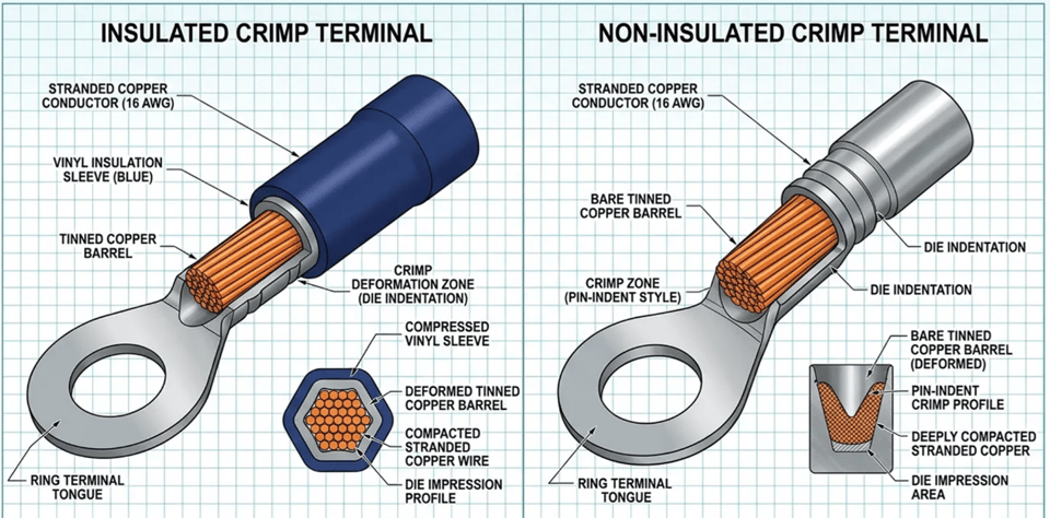
Insulated vs Non-Insulated Terminals
What Are Non-Insulated Terminals? Non-insulated terminals are bare-metal connectors — typically made of copper or brass — designed for simplicity and affordability. They are ideal for enclosed systems, sealed control boxes, and cost-sensitive applications. They are compact, easy to crimp, and effective when external protection is already in place. However, they require precise crimping and may expose wires to shorts in harsh conditions. What Are Insulated Terminals? Insulated terminals have protective vinyl, nylon, or heat-shrink sleeve molded around the crimp barrel, providing electrical isolation, strain relief, and environmental protection. Insulated terminals feature a protective sleeve around the barrel — often color-coded (red, blue, yellow) by wire gauge. They are ideal for exposed environments with moisture, vibration, or corrosion, offering enhanced safety, faster installs, and reduced wiring errors. Types include PVC, nylon, and heat-shrink for added durability. Key Differences Insulated terminals protect against accidental contact, moisture ingress, and vibration-induced shorts; non-insulated terminals rely on the enclosure or secondary sleeving for protection. Standard color coding follows IEC and UL conventions: • Red: 22–16 AWG / 0.5–1.5 mm² • Blue: 16–14 AWG / 1.5–2.5 mm² • Yellow: 12–10 AWG / 4–6 mm² Due to the additional insulating material and manufacturing processes, insulated terminals are generally more expensive than their non-insulated counterparts. The extra insulation may also require more space, which can be a limitation in applications with tight wiring constraints. Crimping Tool Requirements Using a non-insulated crimping die on an insulated terminal punctures the sleeve, creating a shock and short-circuit hazard — always match the die to the terminal type. When to Use Each Type Terminal Type Best For Protection Crimp Tool Non-Insulated Budget / Enclosed Applications Low Standard Crimp Tool Insulated (PVC/Nylon) General Purpose Use Medium Insulation-Specific Tool Heat Shrink Harsh Environments High Heat + Precision Crimp
7/20, 2026
read more
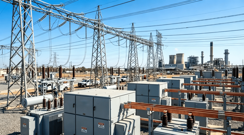
High Voltage vs Low Voltage Terminals ——10 kV / 35 kV Applications
1. Why Voltage Classification Matters Voltage classification serves three critical purposes: • Safety Standardization: Different voltage levels require specific insulation, protective equipment, and handling procedures to prevent electrical hazards. • Equipment Compatibility: Manufacturers design equipment for specific voltage ranges, ensuring proper operation and longevity. • Efficiency Optimization: Higher voltages reduce transmission losses over long distances, while lower voltages are safer for end-user applications. 2. IEC Standard Voltage Classification The IEC standards, particularly IEC 60038 and IEC 61140, are used globally outside North America. Under IEC: • Low Voltage (LV): 50 V to 1,000 V AC or 120 V to 1,500 V DC • Medium Voltage (MV): 1 kV to 35 kV (sometimes extended to 52 kV) • High Voltage (HV): 35 kV to 230 kV • Extra High Voltage (EHV): 230 kV to 800 kV 3. Medium Voltage Systems — 10 kV Medium voltage systems operate between 1 kV and 35 kV (IEC). This classification serves as the critical link between high-voltage transmission and low-voltage distribution networks. • Efficiency: Significantly reduced transmission losses compared to low voltage. • Distance: Can transmit power economically over 5–50 km. • Current: Lower current for equivalent power, reducing conductor size requirements. • Insulation: Requires enhanced insulation and specialized equipment. • Switching: Needs specialized switchgear and protection devices. The higher energy levels at medium voltage mean that accidents can be catastrophic, making strict adherence to safety standards absolutely critical. 4. High Voltage Systems — 35 kV High voltage systems operate between 35 kV and 230 kV (IEC). High voltage minimizes transmission losses over long distances. Power loss = I²R, so higher voltage = lower current = lower losses. However, high voltage is dangerous and impractical for end-use applications. Medium voltage (1 kV–35 kV) bridges generation and distribution: MV systems enable efficient power distribution before stepping down to safe levels for consumers. 5. Comparison: LV vs. 10 kV vs. 35 kV Terminals Parameter Low Voltage (≤1 kV) Medium Voltage (10 kV) High Voltage (35 kV) IEC Range 50 V – 1,000 V AC 1 kV – 35 kV 35 kV – 230 kV Insulation Req. Basic (PVC / XLPE) Enhanced XLPE, stress control required Heavy-duty XLPE, multiple shielding layers Transmission Distance Short-distance, buildings 5 – 50 km Hundreds of km Safety Requirements Standard PPE, basic precautions Strict protocols — accidents can be catastrophic Strict protocols — accidents can be catastrophic Switchgear Standard circuit breakers (MCB / MCCB) Specialized MV switchgear & protection devices Specialized HV switchgear & protection devices
7/13, 2026
read more
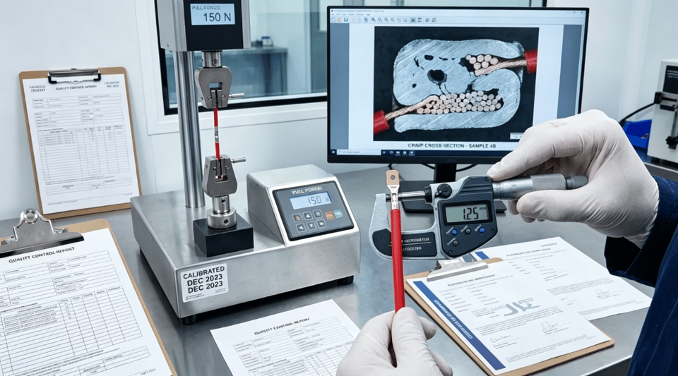
Cold Crimp vs Solder Terminals ——Which Is More Reliable?
1. How Crimp Connections Work A crimp connection is formed by mechanically compressing a metal terminal around a stripped wire conductor using a dedicated crimping tool. When executed correctly, the terminal and wire strands are cold-welded together, creating a solid mechanical bond and a stable electrical interface. Crimping is widely used across industries such as automotive manufacturing, industrial automation, renewable energy systems, and heavy machinery. Its popularity is largely driven by its repeatability and suitability for large-scale production environments. 2. How Solder Connections Work Soldering involves melting and cooling an alloy composed of lead, tin, brass, or silver into solder cups to bond a wire conductor to a contact. This method is typically recommended for general-duty and industrial applications that require reliable signal and power connections. Unlike crimp terminations that require specialized tools, nearly any size wire and solder contact can be terminated with a basic soldering kit. 3. Advantages of Crimp Connections A properly executed crimp forms a gas-tight connection, preventing oxygen and moisture from reaching the conductor. This significantly reduces the risk of corrosion, oxidation, and increased contact resistance over time. Crimped terminals offer superior resistance to vibration, shock, and mechanical stress. This makes them especially suitable for dynamic environments such as vehicles, industrial equipment, and power distribution systems. Crimping is also more consistent than soldering, which can vary according to the method used or the skill level of the technician. 4. Limitations of Solder Connections Solder joints are inherently rigid. Under vibration or repeated mechanical stress, soldered connections are more prone to cracking or failure compared to crimped joints. Soldering is labor-intensive and time-consuming, which limits its efficiency in high-volume manufacturing. Quality is also operator-dependent and can vary according to method or technician skill. Specifying crimp-then-solder because 'both is better' guarantees failure. Soldering a crimp anneals the cold-worked copper, reducing tensile strength by 60% while guaranteeing stress concentration. 5. Industry Standards Favor Crimping Crimping delivers superior reliability over soldering in high-vibration, thermal cycling, and harsh-environment applications. Industry standards including SAE/USCAR-21, IEC 60352-2, and IPC/WHMA-A-620 mandate crimped connections for automotive and aerospace applications where a 15-year service life under extreme conditions is non-negotiable. 6. When Soldering Is Still Preferred Soldering remains valuable in electronics and specialized applications where precision is paramount. Soldered joints provide low contact resistance, which is beneficial for signal transmission in sensitive electronic circuits. Soldering allows for fine, detailed work, making it suitable for densely packed electronic components and intricate wiring layouts. 7. Comparison Summary Parameter Cold Crimp Terminal Solder Terminal Connection Method Mechanical compression (cold weld) Thermal fusion with alloy (Sn/Pb/Ag) Vibration Resistance Excellent — flexible at stress point Poor — rigid, prone to cracking Moisture / Corrosion Gas-tight seal — highly resistant Open joint — susceptible to oxidation Production Speed Fast — automation compatible Slow — labor-intensive Quality Consistency High — tool-controlled Variable — operator-dependent Best Application Automotive, aerospace, industrial, EV PCB, electronics, low-volume, precision signal
7/6, 2026
read more
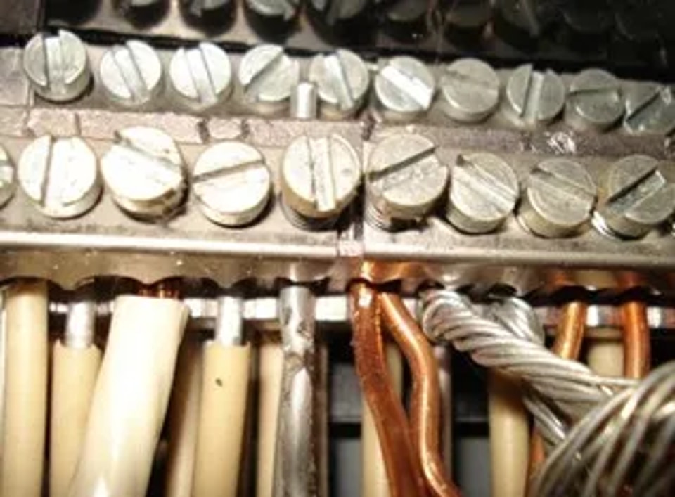
Why Copper and Aluminum Conductors Should Not Be Directly Connected
In electrical wiring systems, copper and aluminum conductors should never be directly connected without proper transition methods. Although both are widely used conductive materials, their physical and chemical differences can create serious reliability and safety problems. 1. Galvanic Corrosion Copper and aluminum have different electrochemical properties. When they are connected in the presence of moisture or air, galvanic corrosion occurs. Aluminum corrodes much faster, forming an oxide layer that increases resistance and causes overheating. 2. Different Thermal Expansion Rates Aluminum expands and contracts more than copper during temperature changes. Repeated heating and cooling cycles can gradually loosen the connection, increasing resistance and generating excessive heat. 3. Mechanical Instability Copper is harder than aluminum. Under pressure, soft aluminum wire can deform or “creep,” reducing contact pressure over time. This may lead to loose joints, arcing, voltage drops, and unreliable conductivity. 4. Fire and Safety Risks A poor copper-aluminum connection may cause: ● Overheating ● Melted insulation ● Sparking or arcing ● Electrical fires Because of these risks, direct connections are considered unsafe in many electrical applications. Recommended Solutions Safe connection methods include: ● Bimetallic copper-aluminum connectors ● Tin-plated terminals ● Welding or Ultrasonic Bonding ● Transition Adaptors or Terminal Blocks These methods prevent corrosion, maintain stable contact pressure, and improve long-term reliability. Conclusion Directly connecting copper and aluminum conductors can result in corrosion, loose connections, overheating, and fire hazards. Using proper transition connectors and approved installation methods is essential for electrical safety and system durability.
6/17, 2026
read more
Why Does Heat Shrink Tubing Crack?
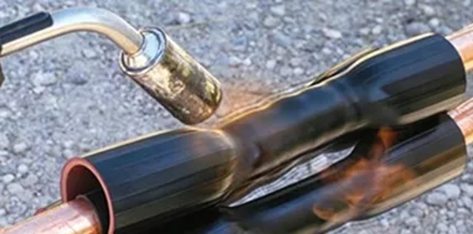
Heat shrink tubing is widely used for insulation, cable protection, and strain relief. However, under certain conditions, it may become brittle, split, or crack over time. 1. Overheating During Installation Excessive heat can damage the tubing material and reduce its flexibility and strength. Common signs include: ● Surface cracking ● Burn marks ● Blistering ● Brittleness To prevent overheating: ● Keep the heat source moving ● Avoid heating one area too long ● Apply heat gradually Heat guns usually provide more controlled heating than open flames. 2. Incorrect Tubing Size Using tubing that is too small may overstress the material during shrinking and cause splitting. If the shrink ratio is incorrect, the tubing may either crack or fail to seal tightly. 3. UV Exposure and Aging Sunlight, moisture, and outdoor weather can gradually degrade some heat shrink materials. Over time, the tubing may: ● Lose flexibility ● Become brittle ● Develop cracks UV-resistant tubing is commonly recommended for outdoor use. 4. Mechanical Damage Sharp cable edges, vibration, repeated bending, or pulling stress can weaken the tubing and eventually lead to cracking. Conclusion Heat shrink tubing commonly cracks because of: ● Overheating ● Incorrect sizing ● UV exposure and aging ● Mechanical stress ● Poor material quality Choosing the correct material and applying heat properly can greatly improve long-term durability and performance.
6/15, 2026
read more
Why Are Some Terminals Tin-Plated?
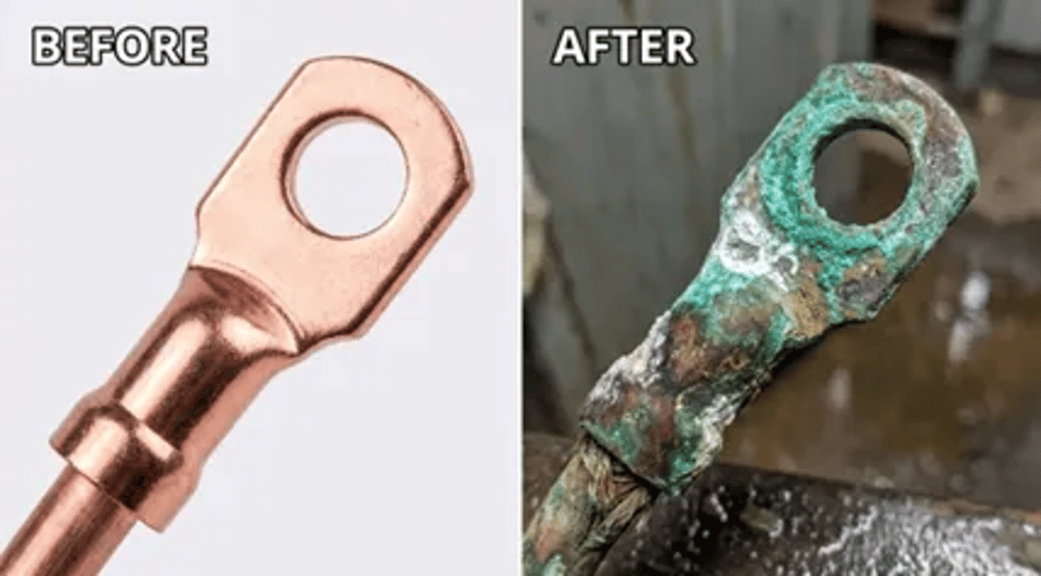
A lighting fixture fails on an offshore platform.An automotive connector corrodes after exposure to road salt.An HVAC system develops voltage drops caused by oxidized wire connectors. These are common electrical failures often caused by one problem: unprotected copper. The Problem with Bare Copper Copper is widely used in electrical terminals because of its excellent conductivity and flexibility. However, when exposed to oxygen, moisture, or salt, bare copper oxidizes quickly. This oxidation increases electrical resistance and may lead to: ● Poor conductivity ● Overheating ● Voltage drops ● Unstable electrical contact ● Premature failure In harsh environments such as marine or automotive applications, corrosion can develop even faster. How Tin Plating Helps Tin plating creates a protective barrier over the copper surface, helping prevent corrosion and maintain stable electrical performance. Compared with bare copper, tin-plated terminals provide: ● Better corrosion resistance ● Improved solderability ● More reliable electrical contact ● Longer service life Tin plating is also cost-effective, making it widely used in automotive, industrial, marine, and consumer electrical systems. Why Plating Thickness Matters If the tin layer is too thin, moisture may eventually reach the copper underneath. If it is too thick, manufacturing costs increase and tin whiskers may form, potentially causing short circuits. Conclusion Tin plating is not just a cosmetic finish—it is an essential protective layer that improves durability, conductivity, and long-term reliability. Without proper plating, copper terminals become far more vulnerable to oxidation, overheating, and electrical failure.
6/8, 2026
read more
Heat Shrink vs Cold Shrink - What's the Difference
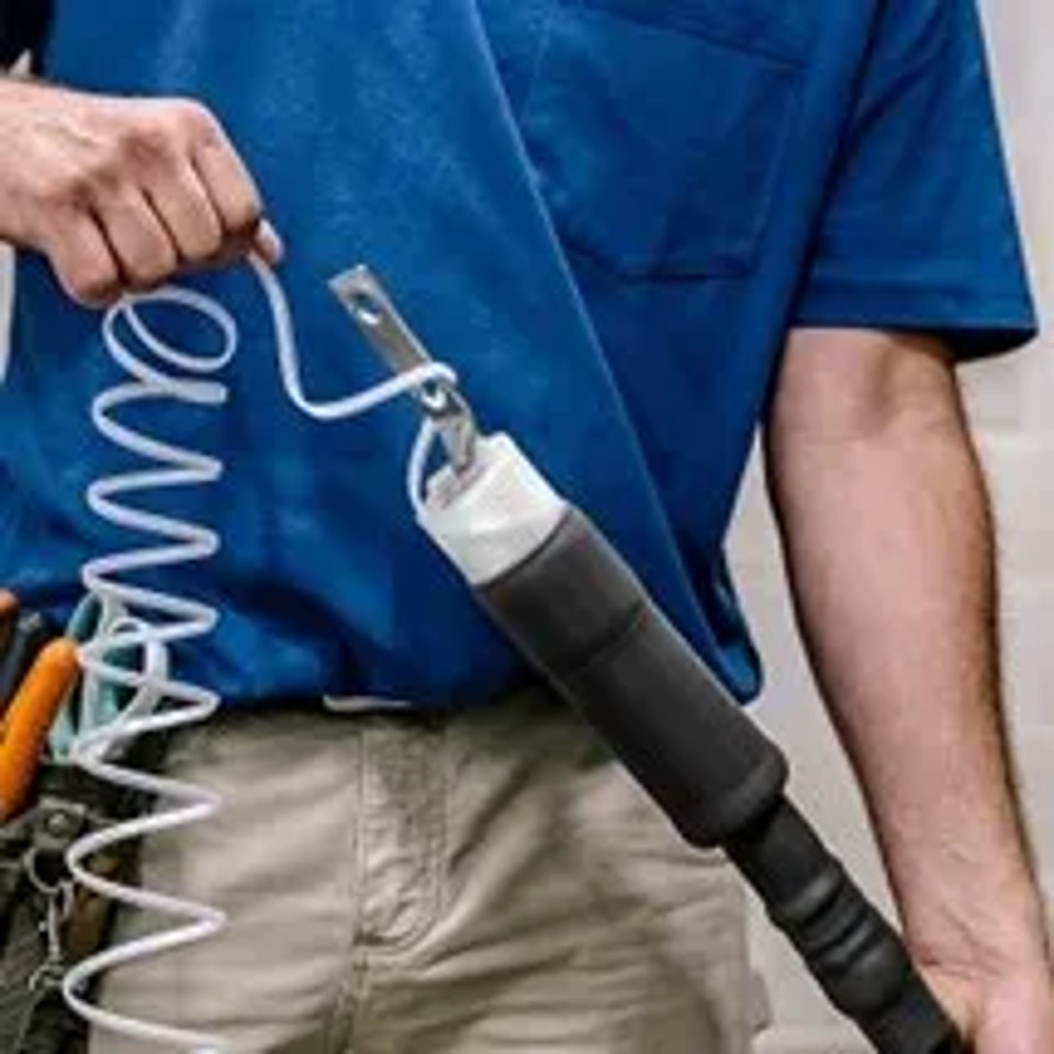
Heat shrink and cold shrink technologies are both widely used for cable insulation and environmental sealing, but they work in different ways. Sealing Method Heat shrink products use external heat to shrink tightly around the cable. Cold shrink products use the natural elasticity of rubber materials to create sealing pressure without heat. Cold shrink materials continue applying inward pressure after installation, creating a flexible “living seal.” Heat shrink products, by contrast, form a more rigid protective layer after cooling. Installation Differences Heat shrink installation usually requires a heat gun or torch and must be heated evenly to achieve proper sealing. Cold shrink products are installed by positioning the accessory and removing the internal support core. No heat or special tools are required. Because of this, cold shrink systems are often preferred in environments where open flames or hot work are restricted. Material Differences Heat shrink products are commonly made from polyolefin thermoplastic materials.Cold shrink products are usually manufactured from silicone rubber or EPDM rubber. These materials affect flexibility, UV resistance, elasticity, and long-term sealing performance. Typical Applications Heat Shrink ● Wire insulation ● Cable repair ● Automotive wiring ● Industrial cable protection Cold Shrink ● Medium-voltage cable systems ● Outdoor installations ● Utility power applications ● Fast field installation environments Conclusion Both technologies provide reliable cable insulation and protection. Heat shrink products are valued for strong mechanical protection and durability, while cold shrink products offer faster installation, flexible sealing, and installation without external heat. The best choice depends on the installation environment, safety requirements, voltage level, and maintenance needs.
5/27, 2026
read more